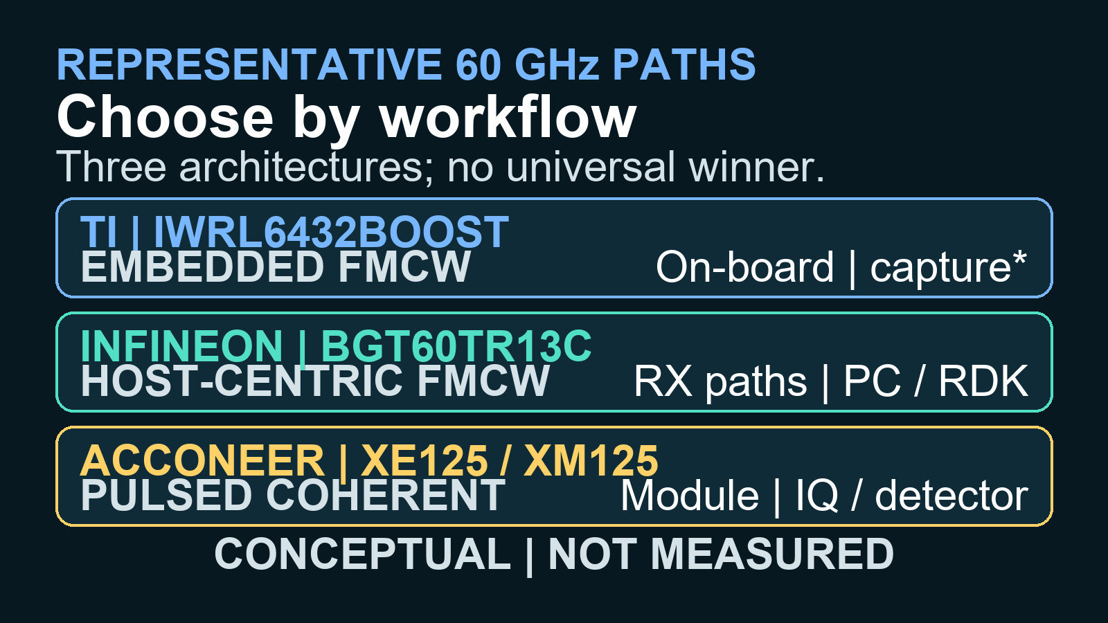
When choosing a 60 GHz radar development platform, choose the TI IWRL6432BOOST when you need embedded FMCW processing and an optional conventional raw-ADC capture path; choose the Infineon DEMO BGT60TR13C when your priority is host-based FMCW experimentation in Python, MATLAB, C, or C++; choose the Acconeer XE125/XM125 when you want a compact pulsed-coherent radar module with embedded distance, presence, or speed processing. The Acconeer path is not the right single-sensor choice for angle estimation, while TI raw capture adds a DCA1000EVM and Infineon’s verified beamforming workflow runs on a PC.
That answer is conditional because these are not three equivalent boards with interchangeable specifications. TI’s representative path is a 2-transmitter, 3-receiver FMCW evaluation module; Infineon’s is a 1-transmitter, 3-receiver FMCW shield on an MCU7 baseboard; and Acconeer’s is a 1-transmitter, 1-receiver pulsed-coherent sensor inside a module, evaluated through a carrier board. The recommendations below are an evidence-based engineering synthesis, not the result of a controlled cross-vendor benchmark.
The decision at a glance
| Representative path | Architecture and array | Documented workflow fit | Decisive limitation |
|---|---|---|---|
| TI IWRL6432BOOST | FMCW; 2 TX, 3 RX; onboard M4F and hardware accelerator | Embedded FMCW demos, processed outputs, CAN-FD, and an optional conventional raw-sample route | Raw capture requires DCA1000EVM; the installed silicon revision and errata matter |
| Infineon DEMO BGT60TR13C | FMCW; 1 TX, 3 RX; shield plus MCU7 baseboard | Host-centric range–angle work with GUI, C/C++, Python, or MATLAB | The default baseboard firmware is a host bridge; evaluation hardware is not a production design |
| Acconeer XE125/XM125 | Pulsed coherent radar; 1 TX, 1 RX; A121 plus an STM32 MCU in XM125 | Compact embedded distance, presence, speed, and phase-sensitive experiments | No angle from one A121 sensor; Sparse IQ is not a conventional FMCW ADC cube |
Start with the required measurement, not the vendor
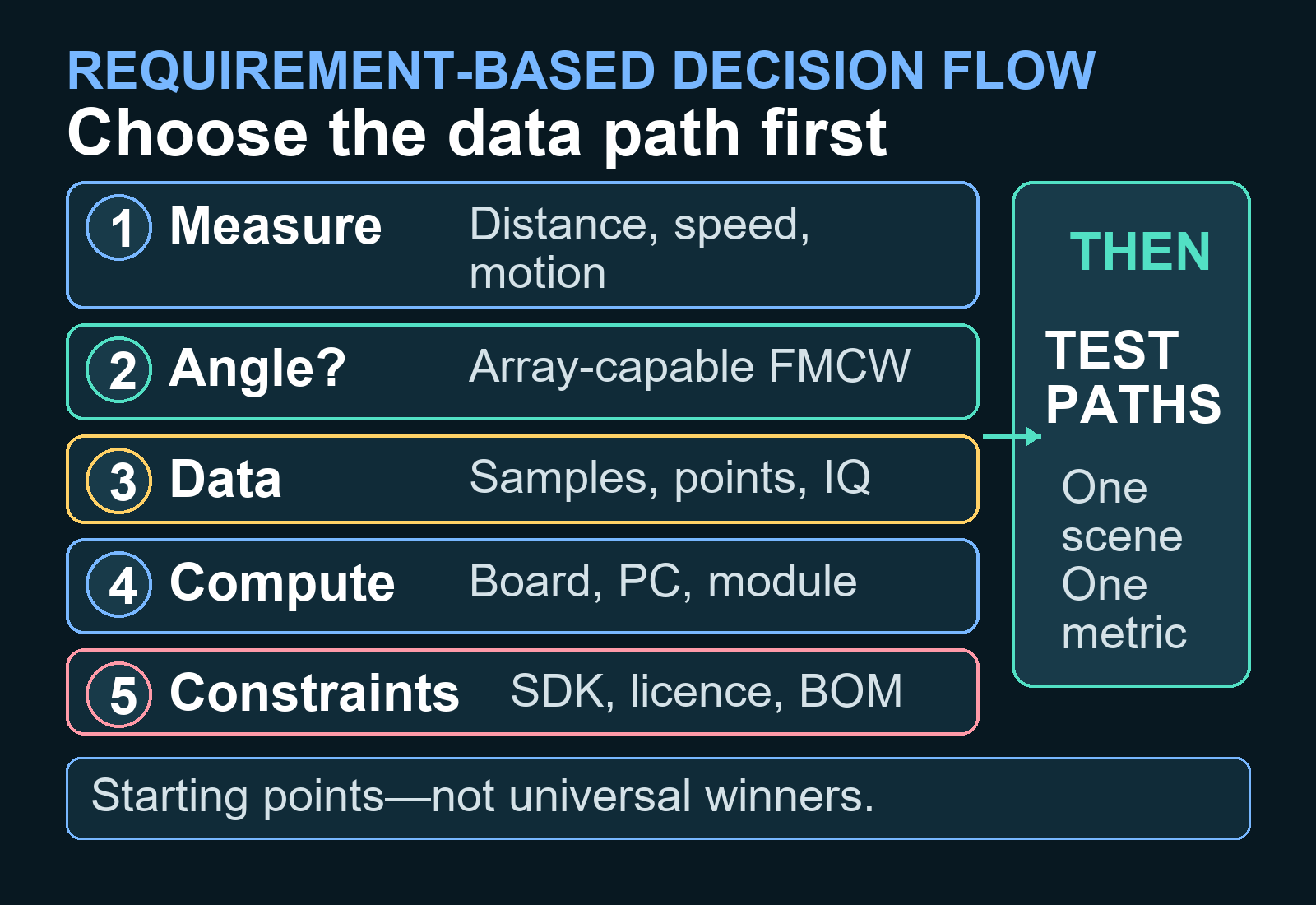
Before comparing boards, write down the observable: distance, radial speed, fine displacement, azimuth, elevation, a point cloud, or an application decision such as presence. If the frequency band itself is still undecided, first review how to choose 24, 60, or 77 GHz radar for human sensing. Once 60 GHz is justified, five questions narrow this comparison quickly.
- Must one sensor estimate angle? If yes, a single 1-TX/1-RX A121 path is excluded. Multiple Acconeer sensors were not evaluated in the verified research.
- What is the earliest data stage your algorithm needs? A point cloud, digitized FMCW samples, and Acconeer Sparse IQ retain different information.
- Where must processing run? Distinguish a PC-based experiment from an algorithm that must execute on the board or module.
- Which software and licence terms are acceptable? Open-source tooling does not necessarily make the complete sensor stack open source.
- Which claim will you verify on your own scene? Vendor-claimed distance and field-of-view figures, and condition-specific power figures, are not a common benchmark.
TI IWRL6432BOOST: the embedded FMCW starting point
What the platform provides
The IWRL6432BOOST combines an onboard FR4 antenna with USB-powered standalone operation. TI documents two transmitters and three receivers, and claims a 120° azimuth field of view and an 80° elevation field of view for the board. The board user guide gives approximate angular resolutions of 29° in azimuth and 58° in elevation from six virtual antenna pairs. These are vendor specifications rather than independent measurements, and they illustrate an important distinction: a broad field of view is not the same as fine angular resolution.
The IWRL6432 datasheet specifies a 160 MHz Cortex-M4F, an 80 MHz HWA 1.2 hardware accelerator, 1 MB of RAM, two transmitters, three real-only receive channels, and a 5 MHz intermediate-frequency bandwidth. The accelerator supports operations including FFT, log magnitude, and CFAR; the datasheet does not list an onboard DSP. TI’s MMWAVE-L-SDK supplies drivers, power-management frameworks, AFE programming layers, FreeRTOS and no-RTOS support, examples, configurable demos, and visualisation tools.
For a quick prototype, the board can output processed application data such as point clouds over its standalone path. If the research requires conventional raw ADC samples, TI documents a separate DCA1000EVM route. The conversion to LVDS happens on the board side because the IWRL6432 itself has no LVDS I/O. Budget that capture board, its setup, and its data rate as part of the platform rather than treating raw capture as a built-in USB feature.
The silicon-revision check is mandatory
TI’s December 2025 IWRL6432 silicon errata restricts ES1.0 to 58–62.5 GHz and ES2.0 to 57–63.9 GHz. It also documents possible SNR degradation when a chirp crosses 60 GHz in the presence of a strong near-range reflector. TI says the effect is negligible for bandwidths above 1.5 GHz and recommends avoiding 60 GHz for narrower chirps. Therefore, identify the revision on the unit you will actually use before choosing a waveform or SDK.
Power numbers also need their conditions. The datasheet’s 1.2 mW average presence-detection example uses a duty-cycled 1 Hz, 1-TX/1-RX configuration. A separate 2-TX/3-RX, 2 GHz bandwidth condition lists typical active power of 960 mW or 1,290 mW depending on power topology. These are silicon-level examples at different operating points, not a generic board-power figure or a basis for ranking three vendors.
Choose TI when: the project needs an embedded FMCW path, established point-cloud or presence demos, onboard M4F/HWA processing, CAN-FD, and the option to add conventional raw capture. Do not choose it on TI’s 25 m vendor claim alone, and do not assume the nominal 57–64 GHz span is available on every silicon revision.
Infineon DEMO BGT60TR13C: the host-centric FMCW starting point
Why it is convenient for algorithm work
The DEMO BGT60TR13C combines a BGT60TR13C shield with Radar Baseboard MCU7. Infineon’s board-offerings brief specifies FMCW operation from 58 to 63.5 GHz, a 5.5 GHz bandwidth, one transmitter, and three receivers. It also claims fields of view of ±45° in both azimuth and elevation; these are vendor claims, not independent measurements or angular-accuracy specifications. The baseboard provides a 300 MHz Cortex-M7, 2 MB of flash, and 384 KB of SRAM.
The BGT60TR13C datasheet describes three digitised 12-bit receive paths whose data moves through a FIFO and SPI interface to an MCU or application processor. Infineon’s Radar Development Kit exposes sensor configuration and data access through C/C++, Python, and MATLAB, alongside Radar Fusion GUI and the ifxdaq recording tool. That combination makes the board a strong documented fit for inspecting time-domain FMCW data and iterating host-side algorithms.
Do not mistake the baseboard for a turnkey edge implementation
Infineon’s verified digital-beamforming example connects the board to a PC over USB, retrieves time-domain frames, and computes range–Doppler and range–beam results in Python. It forms 27 beams from −40° to +40°. That is evidence of a host workflow, not proof of angular accuracy, latency, or turnkey execution on MCU7.
The shield user guide says the default MCU7 firmware acts as a bridge to a host, normally a PC, and classifies the board as evaluation or test hardware rather than production or reliability-test hardware. Custom firmware may support a different execution arrangement, but that must be evaluated as a separate engineering task.
Choose Infineon when: a direct documented route to three-receiver FMCW data, range–angle experiments, a desktop GUI, and Python or MATLAB matters more than proving an immediately deployable on-board pipeline. Do not rank it by Infineon’s application-specific “up to 15 m” vendor claim.
Acconeer XE125/XM125: the compact pulsed-coherent starting point
It is not a small FMCW board
Acconeer’s A121 documentation listing describes A121 as a 60 GHz pulsed-coherent radar sensor with one transmitter and one receiver. Its technology overview describes short wavelets around a 60.5 GHz carrier and coherent amplitude-and-phase measurements. That architecture can estimate distance and support fine-motion work, but one A121 cannot determine angle by itself. It should not be described as an FMCW sensor.
The XM125 module integrates A121 with an STM32L431 Cortex-M4 running at 80 MHz, with 128 kB of flash and 64 kB of RAM. It can run an RSS-based customer application on the module or expose register-protocol control to an external host. XE125 adds an evaluation board and USB-C connection. The setup documentation notes that a USB-C cable is not included.
A121 Sparse IQ data is organised into frames, sweeps, range points, and optional subsweeps. The documented buffer condition is the number of distance points multiplied by the number of sweeps being no greater than 4,095 complex samples. Acconeer documents phase-sensitive processing and range–velocity FFTs, while its A121 detector package includes C implementations for distance, presence, and speed. Sparse IQ is useful data, but it is not equivalent to a conventional FMCW multi-channel ADC cube.
Separate the open tool from the complete software stack
Acconeer describes Exploration Tool as an open-source GUI and Python environment. The current XM125/XE125 page at the research access date listed server and SDK version 1.13.0 dated 27 March 2026, but downloads require login and acceptance of the displayed licence. The displayed terms permit specified incorporation and distribution with Acconeer-chipset products; they do not make the complete RSS stack open source. Review the controlling licence from the actual downloaded package before product development or redistribution. Do not publish vendor-comparative A121 benchmark results unless Acconeer has provided written permission and appropriate legal review has confirmed the applicable terms.
Choose Acconeer when: a compact module, standalone distance/presence/speed processing, coherent phase, and simple USB-connected evaluation matter more than single-sensor angle or conventional FMCW sample access. Acconeer’s “up to 20 m” range figure is a conditional vendor claim, not an independently measured result; do not compare it directly with claims made for different targets, waveforms, integration levels, and detection criteria.
Bandwidth math helps—but only for the FMCW platforms
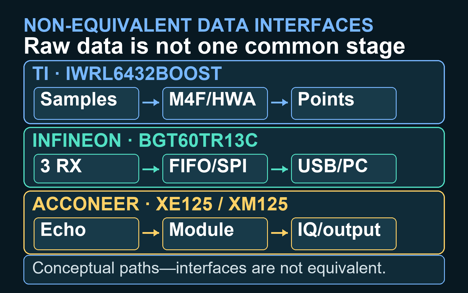
For an ideal FMCW waveform, the configured swept bandwidth sets the approximate range-bin resolution. The comparison below is a set of theoretical calculations that substitutes documented hardware or errata frequency spans for B; those spans are not evidence of configured sweeps or measured performance. The derivation and its assumptions are covered in the guide to FMCW range–Doppler–angle mathematics.
\Delta R = \frac{c}{2B}- Delta R is the ideal range resolution in metres.
- c is propagation speed, approximately 299,792,458 metres per second in free space.
- B is the swept bandwidth actually used, in hertz.
| Documented FMCW frequency span used for calculation | Span used as theoretical B | Calculated ideal resolution | What it means |
|---|---|---|---|
| IWRL6432 nominal 57–64 GHz span | 7.0 GHz | About 2.14 cm | A theoretical span-derived calculation, not a configured sweep or a promise that the full span is usable |
| IWRL6432 ES1.0 errata-limited span | 4.5 GHz | About 3.33 cm | Theoretical calculation from the documented 58–62.5 GHz span |
| IWRL6432 ES2.0 errata-limited span | 6.9 GHz | About 2.17 cm | Theoretical calculation from the documented 57–63.9 GHz span |
| BGT60TR13C board-brief span | 5.5 GHz | About 2.73 cm | Theoretical calculation from the documented 58–63.5 GHz span |
As a reproducible theoretical check, using the documented 5.5 GHz frequency span as B gives 299,792,458 divided by 11 billion, or about 0.0273 metres: 2.73 centimetres. This does not establish that the board was configured to sweep that full span. Windowing, signal-to-noise ratio, antenna response, target geometry, ADC and IF constraints, leakage, and the estimator all affect realised performance. Range-bin resolution is also different from the accuracy of one target estimate or the minimum separation at which two real targets will be detected reliably.
Do not apply this FMCW calculation directly to Acconeer A121. Its pulsed-coherent architecture, profiles, sampling scheme, and Sparse IQ service need to be evaluated with Acconeer’s own measurement model and the intended configuration.
“Raw data” does not mean the same thing on all three paths
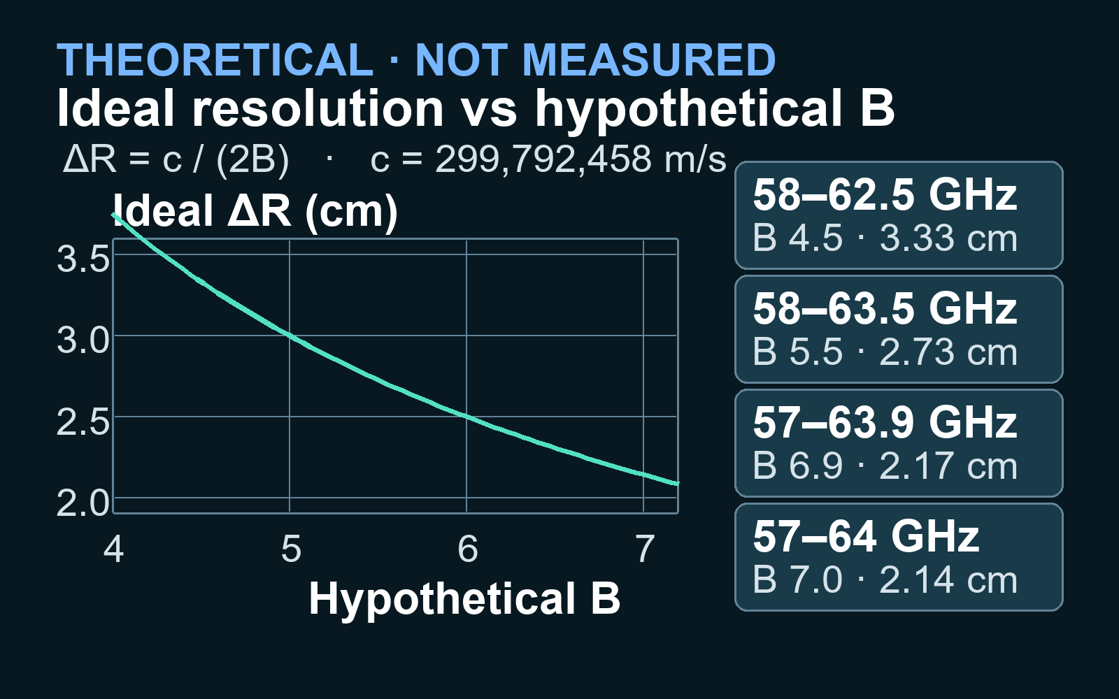
This distinction can decide the purchase before any headline specification does. An algorithm built from raw radar ADC samples to activity labels needs different access from an application that consumes points or detector outputs.
| Platform | Documented data route | Do not assume |
|---|---|---|
| TI IWRL6432BOOST | Processed application output on the standalone board; real ADC samples through RDIF and the separate DCA1000 capture route | That plugging in USB exposes a conventional raw multi-channel stream |
| Infineon DEMO BGT60TR13C | Three digitised time-domain receive paths through FIFO/SPI, with the default MCU7 path bridging data to the PC and RDK | That the verified host beamforming example already runs as a turnkey edge application |
| Acconeer XE125/XM125 | Sparse IQ service frames or higher-level detector results, used on the module or by a host | That Sparse IQ is equivalent to the earliest conventional FMCW ADC stage |
For learned signal processing, custom CFAR, calibration studies, or new beamforming, verify that the required pre-processing stage is actually exposed. For a product prototype that only needs presence or distance, retaining the earliest samples may add throughput and engineering cost without adding value.
Which platform fits common projects?
| Project requirement | Evidence-supported starting point | Qualification |
|---|---|---|
| Embedded FMCW presence or point-cloud prototype | TI IWRL6432BOOST | Confirm silicon revision, memory and compute budget, exact SDK build, and whether processed output is sufficient |
| PC-based FMCW range–angle or algorithm research | Infineon DEMO BGT60TR13C | The documented host workflow is a key consideration; porting to embedded execution is separate work. |
| Compact distance, presence, speed, or coherent fine-motion module | Acconeer XE125/XM125 | Suitable when one-sensor angle and conventional FMCW ADC access are not requirements |
| New processing from conventional radar samples | Infineon host route, or TI with DCA1000EVM | Define the exact sample stage, channel count, metadata, sustained rate, and dropped-frame policy before purchase |
| Single-board angle estimation | Evaluate TI and Infineon | Compare physical and virtual antenna geometry, calibration, field of view, sidelobes, and estimator—not TX/RX count alone |
| Higher-compute TI work with a DSP | Evaluate IWRL6844EVM as a separate tier | TI documents four transmit and four receive antennas, a Cortex-R5F, C66x DSP, HWA, and a separate MMWAVE-L-SDK-6 branch; it is not a drop-in IWRL6432BOOST replacement |
What about Acconeer A212 and XE212?
A212 is relevant because Acconeer’s product overview claims three transmitters, four receivers, a 120° field of view, 10° resolution, and conditional range up to 23 m. These are vendor claims, not independently measured results, and the overview provides no public common test protocol. More importantly, the public evidence at the research access date did not establish unrestricted XE212 availability or production-development software rights.
Acconeer described A212 silicon as being in mass production in its July 2026 company reporting, while its XE212 announcement referred to selected customers and broader availability later in 2026. The A212 software page listed an evaluation agreement that restricted the software to internal evaluation. Silicon production, an orderable evaluation kit, and commercial SDK rights are three different gates. Treat A212/XE212 as a time-sensitive watchlist item; before selecting it, obtain current written confirmation from Acconeer covering EVK order eligibility, unrestricted availability, production SDK rights, and governing licence terms.
Specifications that cannot select a winner
- Vendor-claimed maximum distance: the cited TI, Infineon, and Acconeer claims do not share a target radar cross section, waveform, probability of detection, false-alarm rate, update rate, mounting, or environment.
- Power: no matched board-level energy-per-update comparison was found. A duty-cycled silicon example cannot be compared with another platform’s active-board figure.
- Vendor-claimed field of view: it describes where the vendor says the system can observe, not how accurately or finely it can separate angles.
- Antenna count: usable angular performance also depends on element coordinates, multiplexing, aperture, calibration, coupling, sidelobes, and processing.
- Price and availability: no reliable same-region comparison of current price, stock, lead time, or required accessories was established. Obtain same-day quotations from authorised channels in one region immediately before purchase, including required capture boards, cables, lenses, adapters, tax, and shipping.
A reproducible selection and benchmark workflow
- Specify the observable and geometry. Record range interval, smallest target separation, radial speed, required azimuth and elevation coverage, mounting, target count, and the smallest motion of interest.
- Name the required data product. Choose among detector decision, distance, Sparse IQ, points, tracks, maps, or conventional samples. Do not write only “raw data.”
- Fix the execution boundary. State what must run on the sensor, module, baseboard, external MCU, or PC, with memory, latency, throughput, and power budgets.
- Build the complete bill of materials. Include capture cards, cables, debug probes, adapters, host storage, licences, and enclosure or antenna constraints. Obtain same-day, same-region quotations.
- Freeze revisions. Record board and silicon markings, firmware, SDK, tool versions, licence, operating system, and configuration files. For IWRL6432, match the errata to the actual silicon.
- Run a proof-of-measurement test. Capture an empty scene, a stationary target, the smallest motion, the fastest motion, and the nearest, farthest, and most oblique required positions. Record dropped frames, phase continuity, saturation, temperature, and metadata.
- Repeat before scaling. Remount the sensor, repeat on another day, and test the intended enclosure and environment before committing to a large dataset or production architecture.
A fair cross-platform experiment must hold the application target, geometry, update rate, duty cycle, processing boundary, output definition, and error metric as constant as the architectures allow. It should report what could not be matched. Until that experiment exists, phrases such as “best range,” “lowest power,” or “most accurate” are unsupported.
Failure modes to catch before purchase
- Buying Acconeer A121 for single-sensor angle estimation.
- Buying TI for raw samples without budgeting for DCA1000EVM and its capture workflow.
- Assuming Infineon’s PC beamforming example proves the same pipeline runs turnkey on MCU7.
- Confusing field of view with angular resolution, accuracy, or the number of resolvable people.
- Ignoring IWRL6432 silicon revision, errata, or an SDK-version mismatch.
- Assuming Exploration Tool’s open-source status applies to the complete Acconeer RSS stack.
- Using evaluation-board availability as evidence of production qualification or finished-product compliance.
- Publishing a comparative Acconeer benchmark before resolving the applicable licence and permission terms.
Regulation and production readiness are separate gates
The verified United States source is the 1 October 2025 annual edition of 47 CFR Part 15, where §15.255 addresses operation within 57–71 GHz and applies different provisions to sub-bands and uses, including field-disturbance sensors and pulsed radar. This does not establish regulatory suitability outside the cited United States rule, for a specific airborne, vehicular, outdoor, or in-cabin deployment, for later rule changes, or for a finished product. Check current local rules and obtain qualified regulatory or test-laboratory review for the final antenna, enclosure, waveform, installation, RF exposure, and use case.
Likewise, an evaluation board is not automatically designed for production reliability, safety, electromagnetic compatibility, or certification. Treat productisation, supply continuity, security, privacy, functional safety, and software licensing as explicit gates after the sensing proof succeeds.
Bottom line
- TI IWRL6432BOOST: a documented starting point for embedded FMCW processing and optional conventional capture, provided you manage silicon revision, errata, and the DCA1000 accessory path.
- Infineon DEMO BGT60TR13C: a documented starting point for host-centric, three-receiver FMCW experiments and direct GUI/Python/MATLAB work.
- Acconeer XE125/XM125: a documented starting point for a compact pulsed-coherent module, embedded detectors, and phase-sensitive work that does not require angle from one sensor or a conventional FMCW ADC cube.
Choose the architecture and earliest required data stage first. Then verify software access, accessories, licences, and regulation. If multiple candidates survive those gates, validate the final choice with a controlled test in the real geometry.
Primary references
- Texas Instruments: IWRL6432BOOST product page, IWRL6432 datasheet, silicon errata, and MMWAVE-L-SDK.
- Infineon: DEMO BGT60TR13C product page, BGT60TR13C datasheet, and Radar Development Kit.
- Acconeer: A121 documentation and software listing, XM125/XE125 documentation, and pulsed-coherent radar overview.
- United States regulation: 47 CFR Part 15 annual edition.