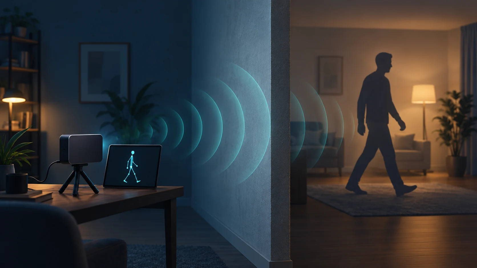
Yes—radio sensing can estimate a person’s pose through some walls. RF-Pose, introduced at CVPR 2018, demonstrated 2D human skeleton estimation from radio reflections. A vision model supplied supervision during training; the trained system used radio input alone, including in its through-wall demonstrations. The output was an estimated pose, with the limitations of the sensing and evaluation setup. [1]
The useful question is what that result lets a researcher claim. A convincing skeleton animation does not tell us the error of each joint, performance in a different building, or whether an application can make a reliable decision from the output. This breakdown separates the demonstrated capability from those next engineering questions.
What does “seeing a person” mean here?
Human sensing contains several tasks that can look similar in a promotional video. Start by naming the output you need.
| Task | Output | What must be evaluated |
|---|---|---|
| Presence detection | Whether someone is present | Missed people and false detections |
| Localization | A person’s position | Position error and lost targets |
| Pose estimation | Locations of body keypoints | Joint placement and person association |
| Activity recognition | An activity label or event | Class errors, missed events and false alarms |
These outputs answer different questions. Knowing that a person is sitting does not locate their wrist. Locating a wrist does not establish whether a movement is clinically significant. An application may combine several tasks, but each stage needs evidence appropriate to its output.
For the broader sensing choice, our radar-versus-camera comparison connects measurement requirements to deployment conditions.
What entered RF-Pose, and what came out?
The implementation used custom FMCW hardware and horizontal/vertical complex RF heatmaps. Two temporal encoders fed a decoder producing 14 keypoint maps from 100 frames (about 3.3 seconds). [2, Sections 3–4]
A keypoint confidence map assigns scores to possible joint locations. Turning those spatial hypotheses into skeletons also requires deciding which keypoints belong to each person. Both placement and association matter when evaluating the output.
This hardware detail matters when considering reproduction. Operating near frequencies associated with Wi-Fi does not make a research radio interchangeable with a household access point. Before choosing equipment, establish what measurements it exposes: sampled waveforms, complex spatial maps, channel estimates, detections or only an occupancy flag. A model cannot consume a representation that the device never provides.
FMCW means frequency-modulated continuous wave. Its frequency sweeps provide range information; an antenna array provides directional information. [3] Our FMCW range–Doppler–angle guide explains the underlying signal-processing axes. A range–angle heatmap should also be distinguished from a time–Doppler spectrogram: their pixels represent different quantities.
Why body parts can disappear from a radio snapshot
A useful physical precursor is RF-Capture. Its authors describe how centimetre-scale radio reflections depend strongly on body-surface orientation: a limb can direct energy away from the receiver. As a person moves, different body parts become prominent in successive measurements. They used multiple snapshots to assemble a coarse human figure. [3]
Think of moving a small mirror under a lamp. You can stop receiving its bright reflection even though the mirror remains in place. The analogy explains directional reflection; a human body is more complicated than a perfect mirror. Weak returns from a limb do not establish that the limb is absent.
For learning systems, this creates an observability problem: how much evidence about a joint exists in the available measurements? Combining time samples can add useful views, while learned relationships between body parts can constrain an estimate. Neither guarantees that every predicted joint is supported equally well. A smooth, anatomically plausible output still needs comparison with an independent reference.
How a camera can teach a radio model
Cross-modal supervision uses paired observations of the same event to transfer information between sensing modalities. Earlier work by Gupta, Hoffman and Malik demonstrated supervision transfer from RGB representations to depth and optical-flow representations. The general opportunity is to exploit a modality with established supervision while learning from another modality whose labels are harder to obtain. [4]
In RF-Pose, synchronized camera observations provide pose supervision for radio observations during learning. After training, the camera is absent from the prediction input. [1]
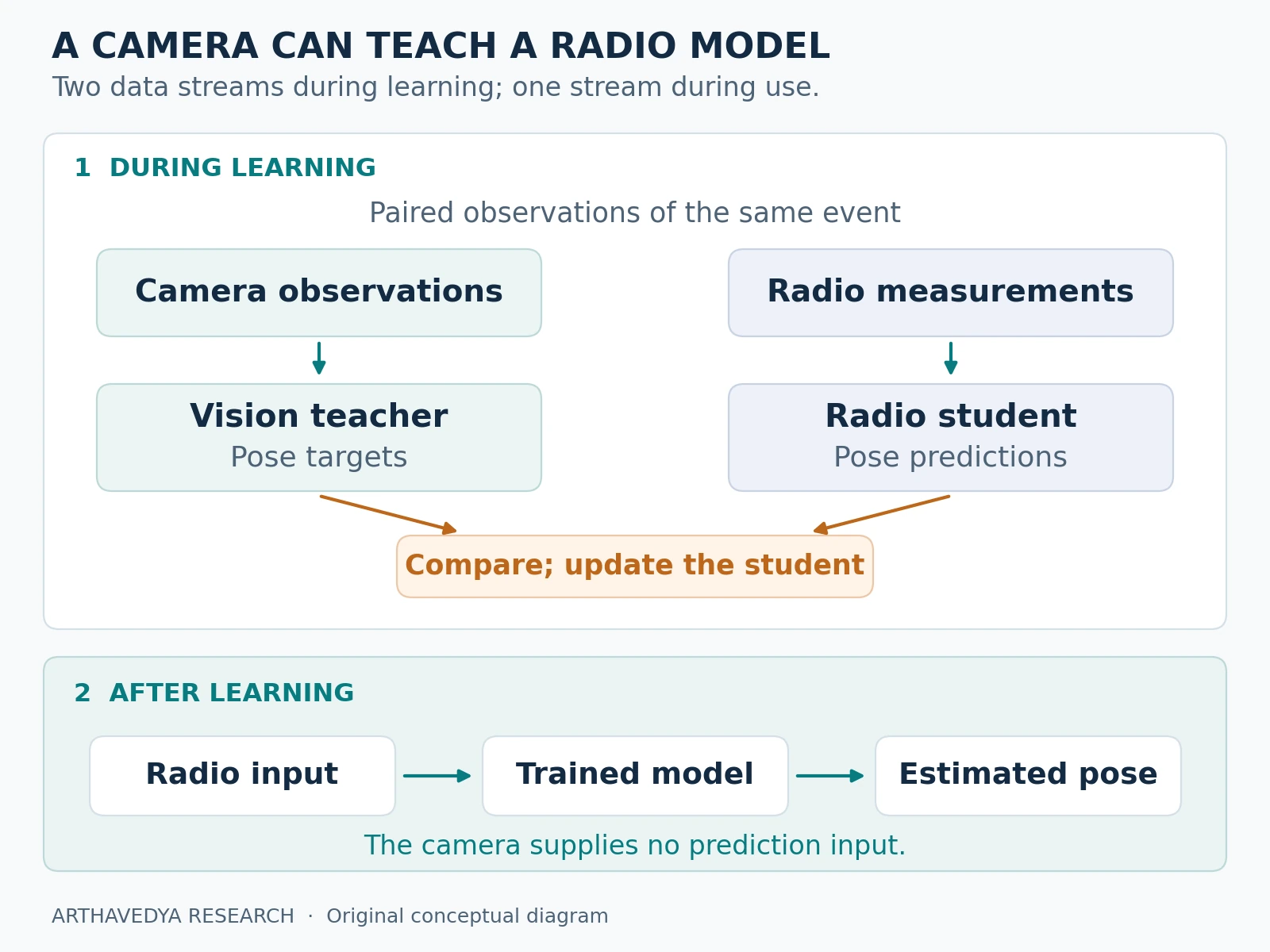
Consider an illustrative training example: a participant raises an arm. A camera-based teacher predicts where the arm’s keypoints lie. The radio student receives the paired radio measurements and adjusts its parameters to produce a more consistent pose prediction. Repeating this across varied examples teaches a mapping between radio measurements and pose targets.
The distinction between a training target and independent ground truth is essential. A teacher prediction can contain mistakes. Agreement with that teacher measures imitation; an independently checked reference is needed to assess whether either prediction is correct.
For a new implementation, inspect the supervision before scaling up training. Check a sample of pose targets, verify temporal alignment and document coordinate calibration. A systematically misplaced wrist target can teach a systematically misplaced wrist. Rejecting every difficult frame can create a different problem: a training set that no longer represents the intended deployment.
How did the researchers check a person hidden behind a wall?
Visible data used a 70/30 train/test split with environments separated. Evaluation annotated 1,000 visible and 1,000 through-wall examples. Eight calibrated cameras supplied hidden-person reference poses, projected into the colocated camera view. Through-wall data were test-only: at most three people/frame. [2, Sections 5–6]
A test camera can therefore have access to the person while the RF sensor’s optical viewpoint remains obstructed. This is a valid way to measure a hidden target, provided the reference observations stay outside the model’s prediction inputs. The instrumentation used to score an experiment does not have to match the instrumentation used by the deployed system.
Keep the same distinction when designing your own dataset. Record which sensors supply inputs, which supply training targets and which supply evaluation references. Then protect the relevant people, rooms and recordings across development and testing. Our guide to leakage, splits and domain shift explains why a held-out room claim and a held-out person claim require different checks.
How to read the reported results
| System and test condition | AP | AP50 | AP75 |
|---|---|---|---|
| RF-Pose, visible | 62.4 | 93.3 | 70.7 |
| OpenPose, visible | 68.8 | 77.8 | 72.6 |
| RF-Pose, through-wall | 58.1 | 85.0 | 66.1 |
Source: Table 1. Through-wall OpenPose entries were dashes. RF-Pose used sequences; the vision baseline used single images. Poor-light images were excluded from quantitative training/testing.
AP is a pose-detection metric, not a joint-correctness percentage
Average precision, or AP, summarizes precision and recall under a matching rule. For keypoints, object keypoint similarity (OKS) assesses predicted joint positions relative to a reference, accounting for person scale and keypoint-specific tolerances. Increasing the OKS threshold demands a closer pose match. AP50 uses a threshold of 0.50; AP75 uses 0.75. The COCO-style aggregate averages across ten thresholds from 0.50 to 0.95. [5]
Consequently, an AP score cannot be translated directly into “this fraction of joints is correct,” centimetres of error or activity-recognition accuracy. A statement about joint-distance error requires a distance metric and a stated coordinate system. A statement about activity recognition requires activity labels and its own evaluation.
Read the table across both conditions and matching strictness. The ordering of the two visible-scene systems changes between the looser and stricter thresholds. Choosing only the favourable column would hide information the reader needs. The through-wall row, meanwhile, concerns a separate test condition; subtracting its AP from the visible row does not isolate a universal causal penalty for inserting a wall.
ArthaVedya’s interpretation: this is evidence that radio measurements can support useful pose inference under visual occlusion. It does not establish equality with every camera system, nor does it supply a present-day hardware comparison. To make either claim, compare appropriate baselines on the same target task, with comparable temporal context and clearly documented test conditions.
Why one successful wall test does not cover every building
“Through a wall” leaves much of the propagation problem unspecified. NIST’s measurements of construction materials examined how attenuation changes with material, thickness and frequency, including concrete, brick, wood and drywall. The measurement programme also included wet materials and reinforced structures. A material label alone is therefore an incomplete description of a radio path. [6]
For an intended installation, record the actual wall construction, the sensor and person positions, and relevant changes in the surroundings. Evaluate that configuration directly. A doorway, a different angle or another propagation path can change the received measurements; a successful nearby example does not certify the required path.
A worked example: the echo crosses the wall twice
Consider a deliberately simplified geometry: transmitter and receiver are on the same side of a wall, and the person is on the other side. The selected echo crosses the wall outward and crosses it again on return. Assume the wall introduces 8 dB of power loss on each crossing, with all other factors held fixed.
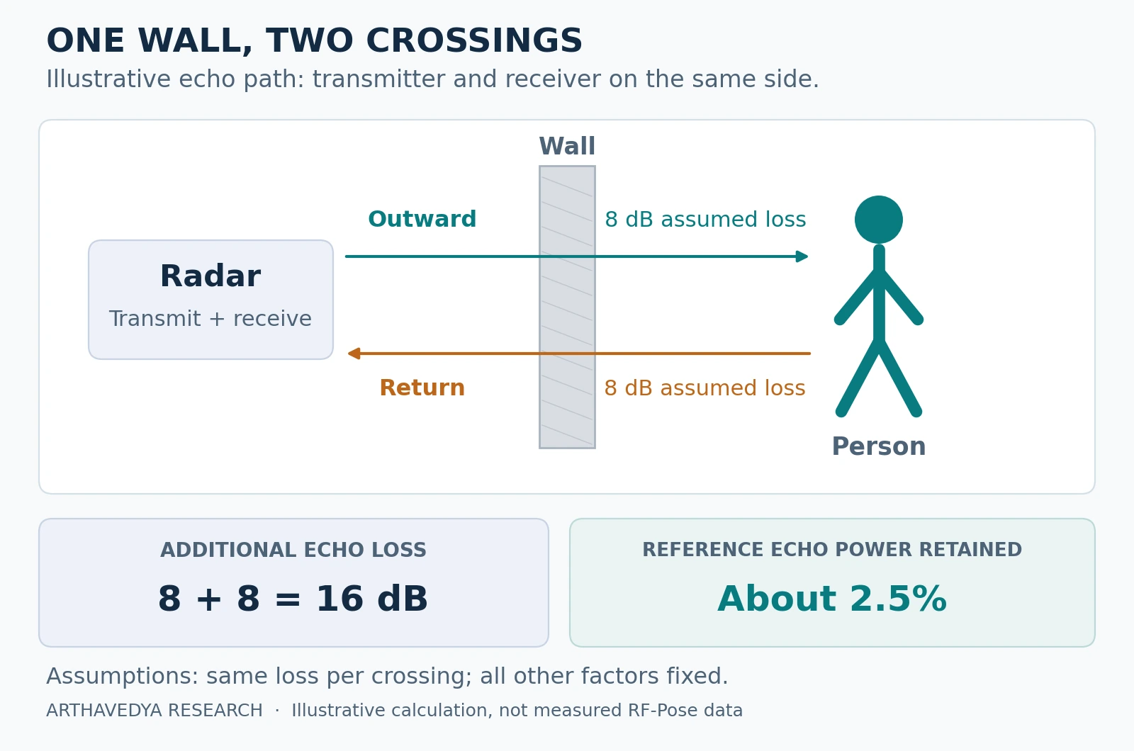
The additional echo loss is 8 + 8 = 16 dB. Converting that loss to a power ratio gives 10−16/10 ≈ 0.025. The echo retains about 2.5% of its reference power—roughly 40 times less. This calculation isolates the assumed wall loss; it is not a measurement of a particular wall, a total radar link budget or a reproduced RF-Pose result.
The example gives a practical reason to inspect signal quality before changing the network. A weak echo may require a different measurement arrangement, more informative observations or a narrower task. A more complicated model alone does not establish that the missing evidence has become recoverable.
Separate resolution, prediction error and response time
Resolution describes separability. Texas Instruments distinguishes range and angular resolution from accuracy: separating nearby reflectors is a different question from estimating one reflector’s position. A learned pose estimate adds another layer, because it combines measurements with a model of the target. [7]
A fine output grid therefore does not certify equally fine measurement resolution. Conversely, a nominal resolution cell should not be treated as a universal lower bound on a fitted target’s position error. For an application, report the actual error distribution, including difficult joints and conditions, instead of substituting grid spacing or a sensor specification.
Response time describes availability. An output timestamp identifies the pose being estimated; it does not necessarily identify when that estimate becomes available. For a temporal model, document the observation window, any future context, buffering, processing and output scheduling. A retrospective animation can look continuous while offering no guarantee about the delay of a live alert.
Test a causal implementation explicitly if a decision must use only measurements already available at that moment. Report the resulting quality and delay together. Do not assume that removing future context preserves an offline model’s performance.
What should remain outside the claim?
- Universal obstacle penetration. The study includes failures with metallic occlusion and closely spaced people. [2, Figure 7]
- Interchangeable 2D and 3D results. The separate SIGCOMM 2018 work RF-Based 3D Skeletons addresses three-dimensional skeletal estimation. Cite that work for its own output and experiments; keep its results distinct from this CVPR study. [8]
- Clinical validation. MIT’s accompanying account discussed potential healthcare uses. Those proposed applications should be distinguished from demonstrated diagnostic or treatment performance. [9]
A health-monitoring application needs an explicit endpoint. Detecting a transition into a sitting pose, detecting a fall and identifying a disease-related gait change are different claims. Choose the reference, participant population, error costs and evaluation duration for the endpoint that will actually guide a decision.
Camera-free sensing still needs privacy decisions
Removing photographs changes what a system records, but a movement history can still contain identifying information. MIT’s account reports a separate experiment identifying people from a group of 100 at approximately 83% accuracy. That result concerns a defined identification experiment, not recognition of any previously unknown person. [9]
For a proposed application, ask what information is necessary to retain. A presence alert, a long skeleton sequence and raw radio recordings serve different purposes. Decide who can access each output, how long it persists, and how participants can understand when sensing is active. These decisions belong in the system design even when the display contains only stick figures.
A practical plan for researchers building on the idea
The most useful follow-up is a small experiment whose success criterion you can state before training. Our radar-HAR dataset collection guide covers the broader capture workflow. For radio pose estimation, add these checks:
- Specify the output. Choose 2D keypoints, 3D positions or an activity decision. Define the coordinate system, required error and response time.
- Confirm the input representation. Verify data access, antenna geometry, sampling, calibration and time alignment with the reference system.
- Audit a small paired capture. Inspect the radio measurements alongside independently reviewed labels. Resolve synchronization and target errors before collecting at scale.
- Reserve the deployment challenge. Hold out the people, rooms, walls or hardware configuration required by the intended claim. Keep evaluation references out of model inputs.
- Report difficult and empty scenes. Include missing detections, false skeletons, person-association mistakes and error distributions. Group correlated frames by recording when assessing uncertainty.
- Test the complete operating system. Measure output delay, sustained processing and the downstream decision’s errors using the actual inference path.
Success might mean reliable torso tracking in one declared environment, even if fine wrist motion remains inaccurate. A narrower result with independent measurements can be more useful than a broad claim supported by a few attractive frames. Publish the conditions that explain where the system works and where the next experiment needs to improve it.
Key takeaways
- Name the sensing task and output before interpreting a skeleton demonstration.
- Separate the model’s inputs, its training supervision and the independent evaluation reference.
- Read pose metrics with their matching rules, test conditions and baselines.
- Evaluate the actual wall path, temporal requirements and downstream decision.
- Treat movement data as potentially sensitive even when no photograph is retained.
References
- [1] Zhao, M., and colleagues. RF-Pose project page. MIT CSAIL; CVPR 2018 overview and demonstrations.
- [2] Zhao, M., and colleagues (2018). Through-Wall Human Pose Estimation Using Radio Signals. CVPR. Author-hosted manuscript.
- [3] Adib, F., Hsu, C.-Y., Mao, H., Katabi, D., and Durand, F. (2015). Capturing the Human Figure Through a Wall. ACM Transactions on Graphics, 34(6), Article 219.
- [4] Gupta, S., Hoffman, J., and Malik, J. (2016). Cross Modal Distillation for Supervision Transfer. CVPR.
- [5] COCO contributors. COCO evaluation implementation. OKS calculation and keypoint AP evaluation parameters.
- [6] Stone, W. C. (1997). Electromagnetic Signal Attenuation in Construction Materials. NISTIR 6055.
- [7] Texas Instruments (2026 revision). Understanding Range and Angular Resolution in mmWave Radar Devices. SWRA841A. Used here for terminology, not RF-Pose performance.
- [8] Zhao, M., and colleagues (2018). RF-Based 3D Skeletons. ACM SIGCOMM; author project page.
- [9] Conner-Simons, A., and Gordon, R. (2018). Artificial intelligence senses people through walls. MIT CSAIL / MIT News, June 12. Institutional account of the research and proposed applications.